Table of Contents
Rietveld refinement of structural distortion-mode amplitudes
Branton J. Campbella, John S. O. Evansb, Francesca Persellib and Harold T. Stokesa
aBrigham Young University, Department of Physics & Astronomy, Provo, Utah 84602, USA. bThe University of Durham, Department of Chemistry, South Road, Durham, DH1 3LE, UK.
Email: branton_campbell@byu.edu, john.evans@durham.ac.uk, stokesh@byu.edu
WWW ISODISPLACE: http://stokes.byu.edu/isodisplace.html
WWW TOPAS: http://www.dur.ac.uk/john.evans/topas_academic/topas_main.htm
Abstract
For any crystal structure that can be viewed as a low-symmetry distortion of some higher-symmetry parent structure, one can represent the details of the distorted structure with a list of distortion-mode amplitudes rather than the traditional list of xyz atomic coordinates. After importing mode definitions from the ISODISPLACE software, TOPAS Academic can now directly refine structural distortion-mode amplitudes. In this article, we demonstrate that the distortion-mode basis is well-suited to a Rietveld refinement of the room-temperature structure of WO3, which has 24 displacive atomic-coordinate degrees of freedom. Only five distortion-mode amplitudes are needed to capture the essential features of this structure.
1.0 Introduction
The details of a subtle superstructural distortion are often very difficult to extract from powder-diffraction data. The added structural complexity of the distorted structure is rarely compensated by the extra information in the low-symmetry powder pattern, which may include only limited peak broadening or splitting and a handful of weak superlattice reflections. This is especially true with data from lab instruments. A typical approach to this type of problem involves iterations over four basic steps: (1) use intuition and experience to select a promising distortion model, (2) transform the parent structural description into the new setting, (3) establish a complicated matrix of bond and/or angle constraints that reduce complexity by allowing only specific geometric distortion patterns, and (4) refine the model against the experimental pattern. With a little luck, a reasonable number of iterations will yield one model that is clearly better than the others. This process is almost always very time consuming, though the pain or pleasure derived largely depends on your interests and objectives!
In this article, we demonstrate that identifying and refining a superstructural distortion can be dramatically simplified by new Rietveld-refinement capabilities that take full advantage of group-theoretical distortion-mode analysis. The combined use of ISODISPLACE and TOPAS Academic eliminates the need for manual structure transformations and many structural constraints, while also streamlining the process of exploring and testing candidate models.
2.0 The distortion-mode basis
The free energy of any crystalline material can be expanded in terms of the order parameters of the irreducible representations of the parent space-group symmetry.1 Most real phase transitions that produce distortions are energetically driven by a relatively small number of these order parameters (often just one). This symmetry-motivated basis of order parameters, which we refer to as the distortion-mode basis, is the most natural basis for studying structural distortions because is allows the essence of most distortions to be captured by the smallest possible number of refinable parameters. As used here, the term “distortion” could refer to any type of physical order parameter, not just an atomic displacement. In the current context, however, we will primarily be discussing atomic displacements, strains, and site occupancies.
A superstructural distortion breaks some of the symmetries of the parent crystal structure. Those parent symmetries that remain in the distorted structure comprise its distortion symmetry2 or isotropy subgroup3 (we use these two terms interchangeably). Thus, the distortion symmetry of a distorted structure is precisely its space-group symmetry, which can be identified by its combination of space-group type, supercell basis and supercell origin. Because the space-group symmetry of a specific structure includes both the symmetry elements of the space-group type and their actual locations within that structure, both the basis and the origin of the supercell are essential information.
Every superstructural distortion is associated with a k-point (or set of k-points) in the Brillioun zone, which is also the location where superlattice reflections will appear in the corresponding diffraction pattern. For a given k-point, the parent space group has a finite number of irreducible representations (irreps), each of which maps its symmetry elements onto an irreducible group of matrices. The dimension of an irrep refers to the dimension of its matrices. The group theory of irreps and irrep matrices is addressed in detail by Bradley and Cracknell,4 though one does not need to be acquainted with irrep theory to follow the concepts presented here. Loosely speaking, each irrep corresponds to a specific set of parent symmetries that can be broken, which in turn determines which subgroups of parent symmetries might be preserved. A physical distortion that breaks only the symmetries associated with a specific irrep is said to be an order parameter of that irrep.
An order parameter of a multidimensional irrep can belong to any one of several different order parameter directions (OPDs) in representation space, each of which breaks only a special subset of the symmetries that the irrep is able to break. The general OPD of an irrep (also called the kernel) breaks as much symmetry as possible. The special OPDs, on the other hand, break less symmetry than the kernel, and result in distortion symmetries that are both subgroups of the parent symmetry and supergroups of the kernel symmetry. For a given k-point and irrep, each available OPD leads to a different distortion symmetry. If (a,b,c,d) is the general OPD of some four-dimensional irrep, then (a,-a,b,b) would be called a special OPD of that irrep. The OPDs of an irrep are somewhat analogous to the Wyckoff sites of a space group – just as an atom at the special (x,0,½) Wyckoff position has fewer degrees of freedom than an atom at the general (x,y,z) position, a physical order parameter that lies along the special (a,-a,b,b) OPD will have fewer structural degrees of freedom than an order parameter that lies along the general (a,b,c,d) OPD. We refer to an OPD's variable parameters as branches, and refer to an order parameter's structural degrees of freedom as distortion modes. Thus, any order parameter with direction (a,-a,b,b) will have two distortion modes: an “a” branch mode and a “b” branch mode.
While irreps and OPDs are purely mathematical abstractions, their order parameters have real physical meaning. A specific distortion symmetry may accommodate many different types of physical order parameters (e.g. strains, displacements, occupancies, etc.), and many distinct order parameters of the same type. Each order parameter will have as many modes as there are branches of the OPD. Each mode is associated with one degree of freedom that has zero amplitude in the undistorted parent structure. Though crystal strain modes (i.e. unit cell parameter changes) are macroscopic, an occupancy mode or a displacive mode is microscopic in nature, and must be associated with a unique atom of the parent structure. Thus, a single microscopic mode may affect many supercell atoms, but only one unique parent atom. For a displacive distortion, there will be as many displacive modes as there are variable atomic-coordinate parameters, all of which will be linearly independent, so that any superstructure that can be described with atomic coordinates can be equally-well described with distortion-mode amplitudes. Atomic coordinates and displacive distortion-modes comprise two equivalent bases of the vector space of all displacive distortions, and are related by a linear transformation.5
The traditional atomic-coordinate description of a given superstructure is entirely independent of any other structure that it may be related to. The distortion-mode description, on the other hand, is a decomposition of the superstructure into the distortion modes of a higher-symmetry parent structure. In this sense, the two bases are quite different, and provide complimentary views of a structure. The distortion-mode basis is considerably more convenient for some applications. In the examples that follow, we will demonstrate that the distortion-mode basis is the most natural basis for exploring phase transitions and refining structural distortions.
3.0 The WO3 phase diagram
The structure of WO3, at first glance, is remarkably simple, consisting of a three-dimensional network of corner-sharing WO6/2 octahedra with a ReO3-like connectivity. In reality, WO3 has a very complicated structural phase diagram6-10 and undergoes at least 6 transitions upon cooling from 1000°C. These transitions involve off-centre distortions of W within the WO6/2 octahedra, as commonly observed for d0 transition metal ions, and coupled tilting of the WO6/2 octahedra, as commonly observed in perovskite-related structures. Howard et al.6 provide a good review the seven known polymorphs of WO3 (see Table 1). These structures can each be described as distortions of a hypothetical cubic (![]() ) parent phase that places W at a(0,0,0) and O at d(½,0,0). The irreps of
) parent phase that places W at a(0,0,0) and O at d(½,0,0). The irreps of ![]() that are relevant to the WO3 phase diagram are located at the G[0,0,0], X[½,0,0], M[½,½,0] and R[½,½,½] points. In describing the order parameters of these irreps, we will refer to the a, b and c axes of the cubic parent structure as d1, d2 and d3, respectively.
that are relevant to the WO3 phase diagram are located at the G[0,0,0], X[½,0,0], M[½,½,0] and R[½,½,½] points. In describing the order parameters of these irreps, we will refer to the a, b and c axes of the cubic parent structure as d1, d2 and d3, respectively.
Table 1: Summary of the ambient pressure WO3 phase diagram. For each phase, we include the temperature range, space-group, supercell shape relative to cubic parent, literature references, Glazer tilt-pattern symbol,11,12 number p of refinable atomic-coordinate parameters, number n of distortion-modes with relatively-large amplitudes, and selected irreps/OPDs of the cubic parent symmetry that are relevant to the distortion. Because the ![]() ,
, ![]() ,
, ![]() and
and ![]() irreps are consistently important across the phase diagram, they are listed wherever they are capable of coupling to a distortion, even when they have no clearly-active (i.e. large-amplitude) modes. Irreps that are not essential to the distortion symmetry are separated from the others by a semicolon, and order-parameter branches giving rise to clearly-active modes are indicated with a bold-face font.
irreps are consistently important across the phase diagram, they are listed wherever they are capable of coupling to a distortion, even when they have no clearly-active (i.e. large-amplitude) modes. Irreps that are not essential to the distortion symmetry are separated from the others by a semicolon, and order-parameter branches giving rise to clearly-active modes are indicated with a bold-face font.
The most important distortion modes induced by ![]() ,
, ![]() or
or ![]() all involve oxygen displacements, whereas those induced by
all involve oxygen displacements, whereas those induced by ![]() or
or ![]() involve tungsten displacements. These irreps also induce other less important (i.e. small-amplitude) modes that are not discussed in detail. Note that the
involve tungsten displacements. These irreps also induce other less important (i.e. small-amplitude) modes that are not discussed in detail. Note that the ![]() octahedral-tilt modes produce anti-phase tilt arrangements, meaning that adjacent octahedra along the tilt axis rotate out of phase, whereas the
octahedral-tilt modes produce anti-phase tilt arrangements, meaning that adjacent octahedra along the tilt axis rotate out of phase, whereas the ![]() octahedral-tilt modes produce in-phase tilt arrangements.
octahedral-tilt modes produce in-phase tilt arrangements.
An ![]() pattern of tungsten displacements directed parallel to the tetragonal axis (d3) is initially present at high temperatures, and corresponds to the off-center shift expected for a d0 cation like W6+. These are followed by the emergence of an
pattern of tungsten displacements directed parallel to the tetragonal axis (d3) is initially present at high temperatures, and corresponds to the off-center shift expected for a d0 cation like W6+. These are followed by the emergence of an ![]() tilt (i.e. rotation) of the WO6/2 octahedra around the tetragonal (d3) axis below 900°C. These two features persist in all of the lower-symmetry distortions. Below 790°C, a monoclinic distortion with unique axis parallel to d1+d2 emerges, which involves a low-amplitude
tilt (i.e. rotation) of the WO6/2 octahedra around the tetragonal (d3) axis below 900°C. These two features persist in all of the lower-symmetry distortions. Below 790°C, a monoclinic distortion with unique axis parallel to d1+d2 emerges, which involves a low-amplitude ![]() mode of tungsten-displacements along the same direction, and a second
mode of tungsten-displacements along the same direction, and a second ![]() octahedral tilt around d1-d2. Below 760°C, the
octahedral tilt around d1-d2. Below 760°C, the ![]() octahedral tilt around d1-d2 disappears, giving rise to an orthorhombic structure that includes
octahedral tilt around d1-d2 disappears, giving rise to an orthorhombic structure that includes ![]() tungsten displacements along d2 and an
tungsten displacements along d2 and an ![]() octahedral tilt around this same axis. Below 400°C, a second
octahedral tilt around this same axis. Below 400°C, a second ![]() octahedral tilt appears, but around d1 this time, giving rise to a different monoclinic structure (same space group as above, but different lattice orientation) with special axis parallel to d2. A third
octahedral tilt appears, but around d1 this time, giving rise to a different monoclinic structure (same space group as above, but different lattice orientation) with special axis parallel to d2. A third ![]() octahedral tilt then develops around d2 below 17°C to form a triclinic structure. Below -40°C, yet another monoclinic phase emerges, with lattice orientation and displacive modes very similar to those of the 760-790°C phase, except for the new appearance of ferroelectric
octahedral tilt then develops around d2 below 17°C to form a triclinic structure. Below -40°C, yet another monoclinic phase emerges, with lattice orientation and displacive modes very similar to those of the 760-790°C phase, except for the new appearance of ferroelectric ![]() oxygen displacements parallel to d3.
oxygen displacements parallel to d3.
The group-subgroup relationships that exist among the distortion symmetries in Table 1 are as follows.
![]() ® P4/nmm ® P4/nnc ® Pbcn ® P21/n ® P
® P4/nmm ® P4/nnc ® Pbcn ® P21/n ® P![]()
![]() ® P4/nmm ® P4/nnc ® P21/c ® Pc
® P4/nmm ® P4/nnc ® P21/c ® Pc
For any pair of structures that have a group-subgroup symmetry relationship, it is possible to decompose the lower-symmetry structure into distortion-modes of the higher-symmetry structure. For two adjacent phases in the diagram, such a decomposition can reveal the primary and secondary order parameters responsible for the phase transition that separates them. In Table 1, we instead prefer to decompose all of the low-symmetry structures into the modes of the hypothetical high-temperature cubic structure, which is not actually observed in nature. We do this because we can, and because it provides a more meaningful picture of the entire phase diagram. The cubic structure proves to be a natural reference point for each of the low-symmetry phases.
In summary, the relatively small number of large-amplitude distortion modes for each phase emphasizes the importance of the distortion-mode basis. Especially for the lowest-symmetry phases, the number of large distortion-mode amplitudes is far smaller than the total number. We find it interesting that most of the active order parameter branches in Table 1 give rise to only one large-amplitude distortion mode.
4.0 Distortion-mode analysis of the P21/n phase of WO3
4.1 Mode decomposition
WO3 has a monoclinic phase that exists between 17°C and 400°C. The structural parameters of this phase at room temperature are listed in Table 2. We will use the ISODISPLACE software tool2 here to transform the P21/n structure of WO3 onto the distortion-mode basis in order to visualize and quantify the displacive modes that give rise to this distortion. ISODISPLACE provides a variety of intuitive methods for exploring distortion symmetries and distortion modes. We invite the reader to treat this section as a tutorial by accessing the ISODISPLACE website and following along.
To enter the cubic parent structure, follow the “Enter structure manually” link on the main page, and then type the space group (![]() ), lattice parameter (a = 3.81 Å) and atom coordinates, W(0,0,0) and O(½,0,0), into the web forms provided. The “View Structure” button on the next page will open a Java applet window that allows you to interactively view the parent structure that you have created. If the structure looks good, close the applet window and use the “Make CIF file” button to save the structure to a file named wo3_cubic.cif. Then go back to the ISODISPLACE home page and repeat the structure-entry process for the monoclinic P21/n structure in Table 2, following the same procedure as before except that you need to choose “Monoclinic cell choice 2” in the section called “Space group preferences”. After visually checking the structure in the viewer applet, save it to a file called wo3_300k.cif. Alternatively, you can download the monoclinic structure from ISODISPLACE website via the following link: http://stokes.byu.edu/wo3_300k.cif.
), lattice parameter (a = 3.81 Å) and atom coordinates, W(0,0,0) and O(½,0,0), into the web forms provided. The “View Structure” button on the next page will open a Java applet window that allows you to interactively view the parent structure that you have created. If the structure looks good, close the applet window and use the “Make CIF file” button to save the structure to a file named wo3_cubic.cif. Then go back to the ISODISPLACE home page and repeat the structure-entry process for the monoclinic P21/n structure in Table 2, following the same procedure as before except that you need to choose “Monoclinic cell choice 2” in the section called “Space group preferences”. After visually checking the structure in the viewer applet, save it to a file called wo3_300k.cif. Alternatively, you can download the monoclinic structure from ISODISPLACE website via the following link: http://stokes.byu.edu/wo3_300k.cif.
Table 2: The P21/n structure of WO3 at room temperature from Woodward et al.8: a = 7.30084(7), b = 7.53889(7), c = 7.68962(8), a = 90, b = 90.892(1), g = 90.
| W1 | 0.2513(6) | 0.0277(7) | 0.2865(5) | O3 | 0.2821(4) | 0.2602(7) | 0.2870(4) |
| W2 | 0.2481(6) | 0.0342(6) | 0.7815(5) | O4 | 0.2107(4) | 0.2602(8) | 0.7310(4) |
| O1 | 0.0008(6) | 0.0366(8) | 0.2116(5) | O5 | 0.2859(6) | 0.0390(6) | 0.0065(5) |
| O2 | 0.9973(6) | 0.4632(8) | 0.2164(5) | O6 | 0.2849(6) | 0.4850(5) | 0.9922(4) |
ISODISPLACE provides four methods of generating distortions. We will start with the mode-decomposition tool (Method 4), which assumes that you already have CIF files containing the parent and distorted structures, and are ready to perform an automatic distortion-mode analysis. Go back to the main page, select “Upload parent structure from a CIF file”, browse to your cubic parent structure (wo3_cubic.cif file) and upload it. Choose the “Monoclinic cell choice 2” option, a setting that will still be in effect later when you need it. This brings you to the “k-point” page (Figure 1). Scroll down to “Method 4” and upload your distorted structure file (wo3_300k.cif).
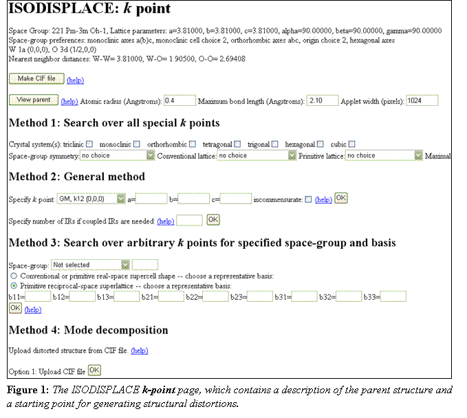
Because the distorted structure has a 2´2´2 supercell relative to the parent cell, enter ((2,0,0), (0,2,0), (0,0,2)) as the supercell basis. This transformation matrix is defined according to ![]() , where ap and as are the absolute parent and supercell lattice vectors. When the decomposition calculation is finished, which may take a few seconds, the Distortion page (Figure 2a) should open in a new window, which contains a summary of the parent structure at the top, followed by a description of the distortion symmetry. The basis, which you entered manually, and the space group type, which comes from the structure file, should be as expected. The supercell origin turns out to be at (½,0,½) in parent-cell coordinates. The size of the primitive unit cell (relative to that of the cubic parent) is indicated as “s=8”. The index of the isotropy subgroup is indicated as “i=96”, which means that parent structure has 96 symmetry elements for every symmetry element in the distorted structure – a very substantial lowering of the symmetry.
, where ap and as are the absolute parent and supercell lattice vectors. When the decomposition calculation is finished, which may take a few seconds, the Distortion page (Figure 2a) should open in a new window, which contains a summary of the parent structure at the top, followed by a description of the distortion symmetry. The basis, which you entered manually, and the space group type, which comes from the structure file, should be as expected. The supercell origin turns out to be at (½,0,½) in parent-cell coordinates. The size of the primitive unit cell (relative to that of the cubic parent) is indicated as “s=8”. The index of the isotropy subgroup is indicated as “i=96”, which means that parent structure has 96 symmetry elements for every symmetry element in the distorted structure – a very substantial lowering of the symmetry.
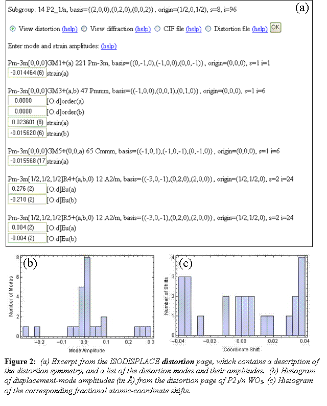
The Distortion page (Figure 2a) contains a list of all of the irreps capable of contributing to the specified distortion symmetry, along with the individual distortion modes induced by each irrep. Note that ISODISPLACE only computes distortion modes associated with three types of order parameters: strains, atomic displacements, and occupancy-related orderings. Irreps that don't induce these order parameter types (but might induce some other kind of order parameter) are grouped together at the bottom of the list. When multiple irreps contribute to a distortion, we say that the irreps are coupled, or that their order parameters are coupled. In general, a more complicated distortion will have a larger number of coupled irreps. To the right of each irrep/OPD in the list, there is a description of the distortion symmetry that would result if that irrep/OPD were to act alone without any coupling.
Most importantly, you can now see exactly how much of each mode couples into the total distortion. ISODISPLACE defines the amplitude of a displacive mode to be the magnitude (in Å) of the largest atomic displacement that it produces. Individual distortion modes are identified with unique labels of the form ![]() [½,½,½]
[½,½,½]![]() (a,b,0)[O:d]Eu(b), which indicates the parent space group (
(a,b,0)[O:d]Eu(b), which indicates the parent space group (![]() ), the k-point [½,½,½], the irrep (
), the k-point [½,½,½], the irrep (![]() ), the OPD (a,b,0), the parent atom [O] and Wyckoff site [d], the point-group irrep (Eu) that breaks the local site symmetry, and the branch of the OPD (b) involved. Compared to intuitive atomic-coordinate labels like O(¼,¼,½+z), this scheme takes some getting used to. But ISODISPLACE mode labels (described in more detail in Ref. [2]) do provide a very concise description of any distortion mode. Observe that, in agreement with Table 1, five of the 24 distortion-mode amplitudes in Figure 2b are clearly much larger than the others. In contrast, the 24 atomic-coordinate shifts (relative to their ideal undistorted parent positions) in Figure 2c exhibit a much more random distribution. These histograms illustrate that structural information tends to be highly concentrated in the distortion-mode basis.
), the OPD (a,b,0), the parent atom [O] and Wyckoff site [d], the point-group irrep (Eu) that breaks the local site symmetry, and the branch of the OPD (b) involved. Compared to intuitive atomic-coordinate labels like O(¼,¼,½+z), this scheme takes some getting used to. But ISODISPLACE mode labels (described in more detail in Ref. [2]) do provide a very concise description of any distortion mode. Observe that, in agreement with Table 1, five of the 24 distortion-mode amplitudes in Figure 2b are clearly much larger than the others. In contrast, the 24 atomic-coordinate shifts (relative to their ideal undistorted parent positions) in Figure 2c exhibit a much more random distribution. These histograms illustrate that structural information tends to be highly concentrated in the distortion-mode basis.
A series of radio buttons near the top of the Distortion page provide several avenues of exploration. First, select “Distortion file” and click “OK” to save the distortion page. You then have the option of quitting and later returning directly to this distortion page via the “Upload distortion file” link on the main page. Next, select “View distortion” and click the “OK” button, which opens an interactive Java applet in a separate window. The applet has one interactive slider per distortion mode that allows you to visualize an individual mode's effect on the structure. Try clicking the “Animate” checkbox to graphically animate the entire distortion. Displacements and strains are represented in the obvious way. Occupancy-related orderings are represented by a variable atomic radius. Other types of order parameters (e.g. anisotropic thermal parameters, etc.) might be accommodated in the future. Abbreviated mode labels save space by omitting information that can be inferred from the distortion page.
From the distortion page, select “CIF file” and click “OK” to export the distorted P21/n structure to another CIF file named wo3_iso.cif. Then open this file in a text editor. In addition to the traditional atomic-coordinate description of the distorted structure, the file contains the complete distortion-mode description. A quick check verifies that there are 24 variable atomic coordinates and 24 distortion modes. This file also includes other information that structure-refinement packages like TOPAS will need in order to directly refine the distortion-mode amplitudes. These are (1) the atomic-coordinate shifts, which all equal zero in the undistorted parent phase, (2) the formula relationships between the distorted atomic coordinates, undistorted coordinates and coordinate shifts, and (3) the 24´24 matrix (in sparse form) that transforms the distortion-mode amplitudes into the coordinate shifts.
4.2 Search restricted by space-group and basis
Now return to the main ISODISPLACE page and assume that we don't yet know the details of the distorted structure, but see evidence from the diffraction data for a 2´2´2 supercell with space group P21/n. Upload your previously saved parent-structure file (wo3_cubic.cif), select “Monoclinic cell choice 2” again, scroll down to “Method 3” within the k-point page, and choose space group #14. Select the “conventional or primitive real-space supercell shape” button and use ((2,0,0),(0,2,0),(0,0,2)) for the supercell basis. Clicking the “OK” button (immediately below the basis fields) leads to a new page (which may take a minute to generate) containing a pull-down list of distortion symmetries that match your choice of space-group type and basis. You should find that there are no less than 6 different origin choices for this basis, each of which results in very different distortion modes! Which one is correct? In general, one needs to explore each possibility, unless there are prior expectations regarding the irreps/OPDs involved. In our case, we already know from the mode-decomposition example above that the correct supercell origin is (½,0,½). Making this selection then takes us on to the distortion page, which looks much the same as before, except that the mode amplitudes are all zero. Given this example, we hope that you will never again place too much faith in a supercell description that doesn't specify the origin!
4.3 The general method (specify k-points, irreps, OPDs)
Return again to the main ISODISPLACE page and assume that you already know which k-points, irreps and OPDs are required to generate the desired distortion symmetry. As in the previous example, upload the cubic parent structure and move on to the k-point page. Method 2 allows us to directly couple an arbitrary selection of commensurate k-point irreps, so almost any physically-realizable distortion involving strains, occupancies and atomic displacements can be accessed. From Table 1, we see that the P21/n structure of WO3 can be generated by coupling ![]() (a,b,0),
(a,b,0), ![]() (a,b,0) and
(a,b,0) and ![]() (0,0,a,a,b,-b). First indicate that you wish to couple 3 irreps and click the corresponding “OK” button, which brings up three pull-down menus containing k-point choices. Select M, R, and X. On the next page, choose the correct irrep for each k-point. The following page contains a list of distortion symmetries (also called isotropy subgroups). If the pull-down menu only contains one item, there will be a “Generate isotropy subgroups” button – click it and wait a minute or two while the menu is loaded. The result is a bewildering list of 46 different distortion symmetries that includes all of the acceptable ways to couple the OPDs available to each irrep. The coupled OPD that we are looking for is just an aggregate of the three OPDs above: (a,b,0) + (a,b,0) + (0,0,a,a,b,-b) ® (a,b,0;c,d,0;0,0,e,e,f,-f). This choice appears about 1/3 of the way down the list, and yields the expected space-group type and origin. The basis, however, is an equivalent monoclinic cell with a different shape. The resulting distortion page is similar to that obtained in the previous examples, except that
(0,0,a,a,b,-b). First indicate that you wish to couple 3 irreps and click the corresponding “OK” button, which brings up three pull-down menus containing k-point choices. Select M, R, and X. On the next page, choose the correct irrep for each k-point. The following page contains a list of distortion symmetries (also called isotropy subgroups). If the pull-down menu only contains one item, there will be a “Generate isotropy subgroups” button – click it and wait a minute or two while the menu is loaded. The result is a bewildering list of 46 different distortion symmetries that includes all of the acceptable ways to couple the OPDs available to each irrep. The coupled OPD that we are looking for is just an aggregate of the three OPDs above: (a,b,0) + (a,b,0) + (0,0,a,a,b,-b) ® (a,b,0;c,d,0;0,0,e,e,f,-f). This choice appears about 1/3 of the way down the list, and yields the expected space-group type and origin. The basis, however, is an equivalent monoclinic cell with a different shape. The resulting distortion page is similar to that obtained in the previous examples, except that ![]() ,
, ![]() and
and ![]() have been moved to the top of the irrep list.
have been moved to the top of the irrep list.
4.4 Filtered search over special k-points
A special k-point search allows one to conveniently explore any distortion symmetry that can be generated by a single irrep at a special k-point of symmetry. The P21/n structure of WO3 requires coupled irreps, and cannot therefore be used in this example.
In summary, ISODISPLACE provides several different methods of generating distortion symmetries: (1) a filtered search over special k-points, (2) a general selection of coupled k-points/irreps/OPDs, (3) a search restricted by space-group type and basis, and (4) the automated decomposition of a known structure into distortion-mode amplitudes. Regardless of which technique is used, the resulting distortion can be saved into a CIF file that contains computer-friendly instructions for refining distortion-mode amplitudes. Such a refinement is the topic of the next section.
5.0 Distortion-mode refinements
We now proceed to illustrate a distortion-mode refinement using laboratory X-ray data collected on a sample of predominantly monoclinic WO3 (P21/n) which was slow cooled from 1000 ºC as described by Woodward et al.8 Data were recorded at 300 K using a Bruker d8 diffractometer equipped with a LynxEye position sensitive detector. A conventional Rietveld refinement used a total of 50 parameters: 24 xyz fractional coordinates, 1 isotropic displacement parameter per atom type, 4 cell parameters, a scale factor, a height correction, 6 parameters of an asymmetric pseudo-Voigt peak shape function and the terms of a 12th order polynomial background function. A final profile weighted R-factor of Rwp = 14.1 and RBragg = 3.1 % was achieved. Though the structure also has 24 displacive mode amplitudes, we observe that most of the structural information is concentrated within a mere handful (i.e. 5) of these modes.
Distortion-mode refinements can be performed in a straightforward fashion using the menus/macros incorporated in the jEdit TOPAS interface and the wo3_300K.cif file described in Section 4.1 above. See http://www.dur.ac.uk/john.evans/topas_academic/jedit_main.htm for more information about this interface. As shown in Figure 4, a series of menu items lets you create an input file for distortion-mode refinements with just four mouse clicks:
- Select Data File: allows you to browse for one of a number of TOPAS-supported data file formats (.raw files, .xy, .xye, .rd, etc) and writes corresponding lines to the .inp file.
- Instrument/Corrections: introduces lines describing the diffractometer wavelength and geometry. Common laboratory setups are included as choices, or the diffractometer can be described from scratch.
- http://www.dur.ac.uk/john.evans/topas_academic/jedit_main.htm: allows one to import a .cif file created by ISODISPLACE or else read in a previously prepared .str distortion-mode file (TOPAS format). With the former choice, the macro runs a small executable (isociftotopas.exe) which sits in the main TOPAS directory to convert the .cif to .str format, and then imports the results.
- ®TA: saves the file with an automatically-generated logical name and sets this as the file that TOPAS Academic (TA) will read from.
These “four clicks” will set up a command file containing everything needed for a sensible default Rietveld refinement. With one more click on the “TA” icon, one can launch TOPAS and perform the distortion-mode refinement. One can, of course, further modify the .inp file, either manually or by using the other built-in TOPAS-related menus. If one already has a .inp file set up for the system in question, isociftotopas.exe can be used independently to create distortion-mode-specific instructions. See http://www.dur.ac.uk/john.evans/topas_academic/jedit_setup.htm for a full description of how to prepare jEdit for use with TOPAS and how to obtain menus which create .inp files for most common procedures (Rietveld refinement, Pawley refinement, Indexing, time of flight refinements, distortion-mode refinements, etc) is available on line . A tutorial with example data sets for a simple distortion-mode refinement of LaMnO3 (http://www.dur.ac.uk/john.evans/topas_workshop/tutorial_isoriet.htm) is also available. The jEdit menus contain “help” links which direct the user to these sites.
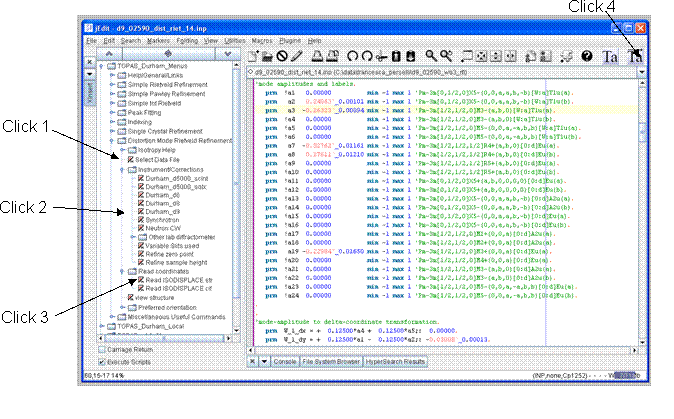 Figure 4: Screen shot of distortion-mode refinement menus in jEdit. The minimum “four clicks” required to prepare and perform a distortion-mode refinement are annotated. The colour-coded .inp file on the right shows the amplitudes of each of the 24 displacive distortion modes of the monoclinic structure of WO3 at 300 K.
This straightforward process produces a .inp file in which each mode amplitude is set up as a refinable parameter labelled a1 – an for brevity (though the full mode label is listed alongside). Atomic-coordinate shifts (e.g. dy) are expressed in TOPAS syntax using equations of the form:
prm W_1_dy = + 0.125*a1 -- 0.125*a2;: -0.00308
where the number after the colon indicates the derived value and is updated on refinement. Atomic coordinates are then expressed in the form:
site W1 Y = ideal_W_1_y + W_1_dy;
where ideal_W1_yis the fractional coordinate of W1 in the current cell setting appropriate for the high-symmetry structure.
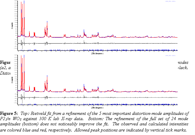
As an example, Figure 5 shows a Rietveld refinement in which only 5 key distortion-mode amplitudes are allowed to refine (i.e. modes a2, a3, a7, a8 and a19 from the .inp file visible in Figure 4; also see the P21/n entry in Table 1). Thus we achieved Rwp = 14.3 % and RBragg = 3.6 % using just 5 structural degrees of freedom rather than the 24 parameters of a conventional refinement. Note that these 5 parameters contribute to shifts in 16 of the 24 xyz coordinates. The need to use at least 5 modes is illustrated in Figure 6, which shows the closest fit to the published P21/n coordinates one can obtain using modes a1, a2, a3 and a4, with and without mode a19. With only 5 modes, all atoms are placed within 0.1 Å of the published positions determined from high-resolution neutron data.
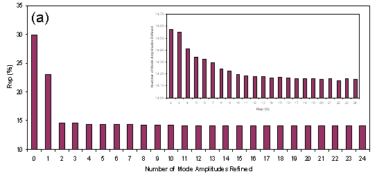
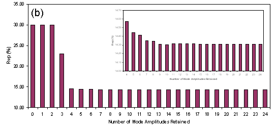
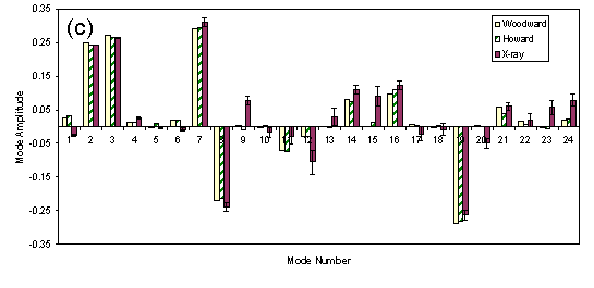 Figure 7: (a) Dependence of Rwp on the number of non-zero distortion-modes refined; (b) dependence of Rwp on number of distortion-modes retained from the structure of Woodward et al.8; © mode amplitudes refined from X-ray data compared to values for structures from Woodward et al.8 and Howard et al.6
The sensitivity of the data to the number of distortion-mode amplitudes retained is shown quantitatively in the histograms of Figure 7a and 7b. Figure 7a shows how the value of Rwp depends on the number of distortion-mode amplitudes used in the refinement. To obtain these graphs a series of refinements were performed in which only the n modes with the highest ratios of amplitude/esd in a refinement using n+1 modes were retained. A good fit can be achieved with 5 mode-amplitudes, whereas beyond ~9 mode-amplitudes, Rwp is approximately constant. The Rwp factors plotted in Figure 7b show the influence of sequentially adding distortion-modes derived from the published structure of Woodward,8 with the largest-magnitude distortions being added first. The Rwp obtained with just 8 distortion modes included is essentially as good as that obtained with 24. It’s interesting to note that Rwp actually increases very slightly in this plot on moving from 10 to 11 distortion-modes. The distortion-mode included at this point (![]() ) involves W motion. The neutron-derived amplitude actually leads to a worse fit to the X-ray data. Histograms in 4a and 4b differ in shape due to the different sensitivities of neutron and X-ray data to distortions involving W and O.
) involves W motion. The neutron-derived amplitude actually leads to a worse fit to the X-ray data. Histograms in 4a and 4b differ in shape due to the different sensitivities of neutron and X-ray data to distortions involving W and O.
Figure 7c gives an indication of how sensitive laboratory X-ray data are to the distortion modes involving oxygen – note that the W:O ratio of scattering powers is 832:82 ~ 108 for X-rays, and that previous structural studies have relied primarily on neutron data. The histogram compares mode-amplitudes from the two neutron refinements with the present X-ray refinement involving the full set of 24 mode amplitudes. The amplitudes of the most important O modes (a7, a8 and a19) refine to values quite close to those determined from neutron diffraction data.
6.0 Conclusions
The internet-based ISODISPLACE software tool allows one to generate and interactively visualize almost any superstructural distortion, and to save the result in a CIF file that contains two complete structural descriptions: traditional atomic coordinates and symmetry-motivated distortion modes, together with the linear transformation between these two bases. With the use of enhanced jEdit macros, TOPAS Academic can now read ISODISPLACE-CIF files, allowing one to refine distortion-mode amplitudes directly using standard optimization algorithms. These tools eliminate the need for manual structure transforms and most structural constraints, and also greatly simplify the process of exploring and testing candidate models. By identifying the important distortion modes, one can successfully perform what might otherwise be a highly underdetermined refinement. As an example, we have demonstrated a distortion-mode Rietveld refinement that captures the primary structural features of the 300 K monoclinic phase of WO3 and shows excellent agreement to laboratory X-ray data using just 5 variable mode amplitudes.
Acknowledgements
We acknowledge Alan Coelho for the development of the TOPAS Academic software package. BJC acknowledges supported from an award from Research Corporation. Lars Peters and Anne Soleilhavoup are thanked for help with data collection.
References
[1] L. D. Landau and E. M. Lifshitz, Statistical Physics, 3rd ed, (Pergamon Press, 1980).
[2] B. J. Campbell, H. T. Stokes, D. E. Tanner and D. M. Hatch, ISODISPLACE: a web-based tool for exploring structural distortions, J. Appl. Cryst. 39, 607-14 (2006).
[3] H. T. Stokes and D. M. Hatch, Isotropy subgroups of the 230 crystallographic space groups, (World Scientific, Singapore, 1987).
[4] C. J. Bradley and A. P. Cracknell, The mathematical theory of symmetry in solids, (Oxford, Clarendon Press, 1972).
[5] H. T. Stokes, D. M. Hatch and J. D. Wells, Group-theoretical methods for obtaining distortions in crystals - applications to vibrational-modes and phase-transitions, Phys. Rev. B 43, 11010-8 (1991).
[6] C. J. Howard, V. Luca and K. S. Knight, High-temperature phase transitions in tungsten trioxide - the last word?, J. Phys. Cond. Matter 14, 377-87 (2002).
[7] T. Vogt, P. M. Woodward and B. A. Hunter, The high-temperature phases of WO3, J. Solid State Chem. 144, 209-15 (1999).
[8] P. M. Woodward, A. W. Sleight and T. Vogt, Structure refinement of triclinic tungsten trioxide, J. Phys. Chem. Solids 56, 1305-15 (1995).
[9] R. Diehl, G. Brandt and E. Salje, Crystal-Structure of Triclinic WO3, Acta Cryst. B 34, 1105-11 (1978).
[10] E. K. H. Salje, S. Rehmann, F. Pobell, D. Morris, K. S. Knight, T. Herrmannsdorfer and M. T. Dove, Crystal structure and paramagnetic behaviour of epsilon WO3-x, J. Phys. Cond. Matter 9, 6563-77 (1997).
[11] A. M. Glazer, The classification of tilted octahedra in perovskites, Acta Cryst. B 28, 3384-92 (1972).
[12] C. J. Howard and H. T. Stokes, Group-theoretical analysis of octahedral tilting in perovskites, Acta Cryst. B 54, 782-9 (1998).
